7 Tips for Choosing the Right Cylinder Boring Machine
Choosing the right Cylinder Boring Machine is a practical decision, not a simple equipment purchase. The machine must match your workshop’s engines, production volume, and measurement standards. A unit designed for small motorcycle cylinders may struggle with heavy-duty diesel blocks. That mismatch creates vibration, inaccurate bores, and unnecessary rework.
Experienced machinists usually inspect more than the advertised boring range. They check spindle rigidity, table travel, fixture stability, cutting speed control, and alignment accuracy. A clear view of the cutting head matters too. Small details matter. Reliable manufacturers should provide technical drawings, operating limits, maintenance guidance, and responsive after-sales support. Independent reviews and verified workshop experience can reveal weaknesses that brochures leave out.
Seven practical tips can make the selection process more dependable. They cover cylinder dimensions, machine compatibility, tooling, precision, operator safety, service access, and total ownership cost. A test cut on a sample block may reveal chatter before installation. Measuring the finished bore with a calibrated gauge remains essential, even when digital controls appear impressive. Technology helps, but it does not replace disciplined inspection.
Not every expensive machine is the best choice. A lower-priced model may become costly when tooling, downtime, or difficult repairs are included. Even experienced teams get this wrong. Workshop conditions also change, so future engine work deserves attention. Careful comparison, honest capacity estimates, and documented measurements will support a more confident investment in a Cylinder Boring Machine.
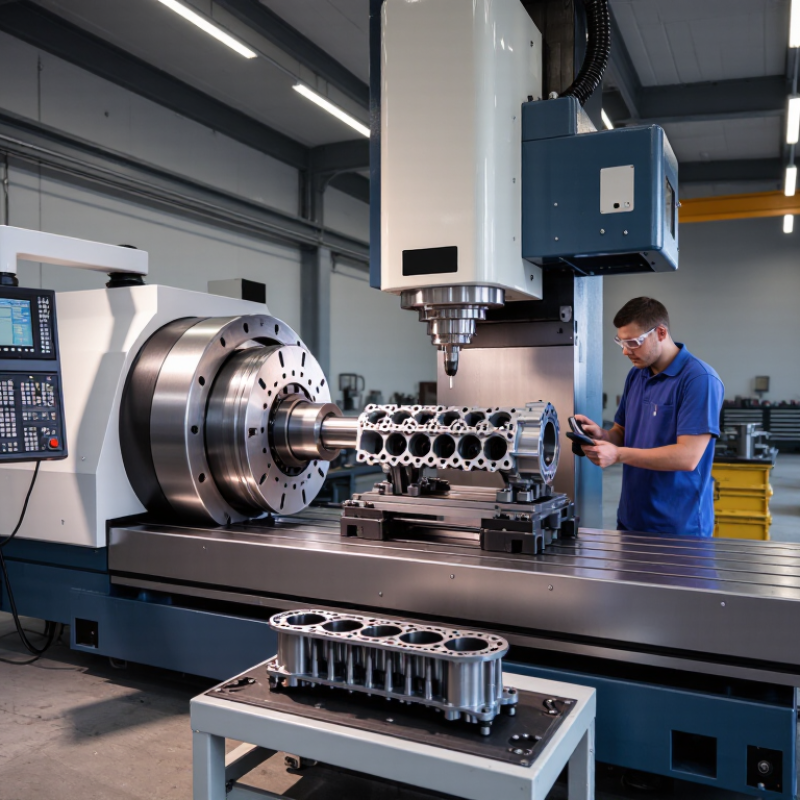
Match Bore Capacity to Engine Blocks: Typical 30–200 mm Range
Choosing the right cylinder boring machine starts with bore capacity, not advertised power. A practical workshop range is 30–200 mm, covering many motorcycle, passenger-car, truck, and industrial engine blocks. Measure the smallest and largest cylinders you actually service. Then add clearance for fixtures, cutter movement, and block distortion. Bigger is not always better.
Check the machine’s minimum bore, maximum bore, spindle travel, and deck-height clearance. Confirm the table can support the block without rocking. A rigid boring bar matters when removing only 0.05–0.10 mm from a worn cylinder. Verify alignment with a calibrated dial indicator. ISO 230-2:2014 provides a recognized framework for checking machine positioning accuracy.
Use suitable pilots and cutters for cast iron and aluminum blocks. Tooling affects the finish more than many buyers expect.
S&P Global Mobility reported an average U.S. vehicle age of about 12.6 years in 2024, supporting continued demand for precision engine repair. However, vehicle age does not predict bore size. I once treated 200 mm as a generous default. That was a mistake. Large capacity increased setup time and reduced control on smaller blocks. Ask suppliers for repeatability data, measurement procedures, and sample test results. A machine that reaches 200 mm but struggles below 50 mm may not suit your daily work. Test your common blocks before purchase.
Verify Accuracy Against ±0.01 mm Targets and ISO 230-2 Testing
Choosing a cylinder boring machine requires more than reading a stated tolerance. A ±0.01 mm target must be verified under controlled conditions. Ask for an ISO 230-2 positioning accuracy and repeatability test for each relevant axis. The report should identify travel length, measurement equipment, temperature, feed rate, and uncertainty. Without these details, the number is difficult to trust.
Inspectors commonly use calibrated laser interferometry or high-precision linear scales. Let the machine reach thermal stability before testing. Measure several points across the working stroke, not only near the center. Record movement in both directions, because backlash can hide behind one-way measurements. Check boring-bar runout separately. A precise axis cannot correct a bent tool or poorly aligned fixture.
Look closely at the raw data.
In practical evaluations, I also compare test results with an actual cylinder bore. Measure the bore at multiple depths and angles after machining, using a calibrated air gauge or coordinate measuring equipment. One weakness in our early checks was ignoring cutting heat; the machine passed a cold test but shifted after repeated cycles. That mistake changed our inspection routine. Request repeat tests after warm-up, and confirm whether compensation remains enabled. ISO 230-2 testing improves confidence, but it does not guarantee every finished bore will meet ±0.01 mm. Operator skill, tooling condition, material stress, and setup rigidity still matter.
Choose Spindle Speed and Feed for Cast Iron and Aluminum Alloys
Choosing a cylinder boring machine starts with matching spindle speed and feed to the material. Cast iron and aluminum alloys punish careless settings in different ways.
ASM International’s Machining Data Handbook lists carbide cutting speeds for gray cast iron near 60–120 m/min, depending on hardness and tooling. For aluminum alloys, published machining tables often recommend approximately 300–600 m/min. Use the lower range when the bore is interrupted or the machine lacks rigidity. For an 80 mm bore, 100 m/min equals about 398 rpm. At 400 m/min, speed rises to roughly 1,592 rpm. The formula is simple: rpm = 1,000 × cutting speed ÷ π × bore diameter.
Feed controls chip thickness and surface behavior. For cast iron, begin around 0.05–0.15 mm per revolution. Aluminum may accept 0.10–0.30 mm per revolution with a sharp, polished cutting edge. CIRP machining research links unstable cutting and poor surface finish to excessive feed, vibration, and inadequate chip evacuation. Keep the boring bar short. Check runout before cutting.
Small adjustments matter.
A practical trial might reduce speed by 10% if chatter appears, then lower feed slightly. That approach is not perfect. Excessive reduction can rub aluminum instead of cutting it, creating built-up edge and smeared bore walls. ASM data also emphasizes that hardness, alloy condition, tool geometry, and coolant change the usable range. Record spindle load, chip shape, and bore size after each pass. Machine capability matters more than a catalog number.
Compare Power, Safety, Automation, and Service-Life Costs over 10 Years
7 Tips for Choosing the Right Cylinder Boring Machine
Compare Power, Safety, Automation, and Service-Life Costs over 10 Years
Power is only the starting point. Match spindle capacity to your typical cylinder sizes, cutting tools, and material hardness. A machine with excessive power may increase energy use without improving accuracy. Check feed stability at low speeds, where finishing quality often changes. Review measured tolerances, not only advertised motor ratings. Ask for test-cut records from comparable workpieces.
Safety deserves practical inspection. Look for guarded moving parts, emergency stops, stable clamping, and clear coolant control. Operators should reach controls without leaning across the boring area. Automation can reduce setup errors through digital feeds, tool-position memory, and job records. However, complicated software creates training demands. I once valued automation highly, then found that poorly trained staff bypassed several useful features. That assumption was too optimistic.
Calculate ownership costs across ten years. Include electricity, tooling, calibration, lubrication, operator training, repairs, and lost production. Estimate routine service intervals and the replacement cost of bearings, guides, and control components. Ask whether technical support provides response times, diagnostic help, and accessible spare parts. A cheaper machine may become expensive after repeated alignment problems. Build three scenarios: normal use, heavy use, and unexpected downtime. Leave room for mistakes. Estimates rarely survive real workshops unchanged. Reliable records, documented maintenance, and verified service procedures usually protect accuracy longer than impressive specifications.