

7 Tips for Choosing the Right Wire Shielding Sleeve
Choosing the right Wire Shielding Sleeve is rarely as simple as matching a diameter. In real installations, heat, vibration, abrasion, moisture, and tight bends all influence performance. A sleeve that looks suitable on a workbench may loosen near a connector or split around a sharp edge. Small details matter.
Henry W. Ott, a respected electromagnetic compatibility engineer, wrote, “The best way to reduce EMI is to prevent it from being generated in the first place.” His principle remains useful when selecting shielding for automotive wiring, industrial controls, data equipment, and sensitive electrical assemblies. Shielding is not a substitute for sound grounding, careful routing, or proper connector design. It works as part of a complete system.
This guide presents seven practical tips for choosing the right Wire Shielding Sleeve. It considers shielding material, coverage, flexibility, inner diameter, temperature resistance, installation method, and long-term durability. Copper and tinned copper offer different corrosion and handling benefits. Braided sleeves may flex well, while dense constructions can provide stronger coverage. Measure the cable bundle under realistic conditions, not when it is neatly compressed on a table.
Expect trade-offs. Maximum coverage can reduce flexibility. A tighter sleeve can improve contact but complicate installation. I have seen teams focus on shielding effectiveness while overlooking termination quality. That mistake is easy to repeat.
Look closely. Test patiently. A reliable choice should fit the cable, environment, and maintenance plan. The best sleeve is not always the most expensive one. It is the one that continues performing after movement, heat, and everyday handling.
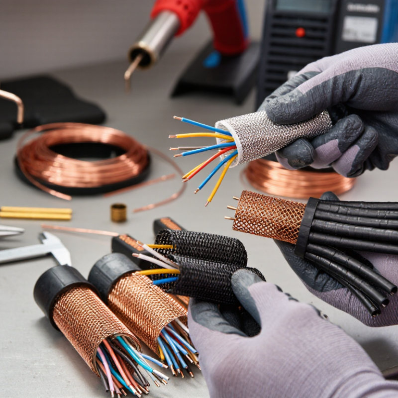
Define the Purpose and Environment of the Wire Shielding Sleeve
Choosing the right wire shielding sleeve starts with its purpose, not its appearance. In field inspections, I first identify the main risk: electromagnetic interference, abrasion, heat, moisture, or movement. A sleeve may reduce signal noise while protecting insulation from sharp edges. These functions often require different materials and structures. A conductive braid can improve shielding but may perform poorly against oil or repeated rubbing. Write down the primary hazard before comparing sleeve designs.
Study the installation environment closely. Record temperature peaks, flexing frequency, bend radius, dust levels, and fluid exposure. Measure the hottest nearby surface, not the average room temperature.
A cable beside a motor may face vibration and electrical noise together. A cable inside a control cabinet may need less mechanical protection but tighter space tolerance. Small details matter, including available clearance and how the sleeve will be secured.
Check the complete assembly, especially the ends. Effective shielding needs continuous coverage and reliable termination. An unconnected conductive braid is mostly decoration. Test the installed cable under bending, vibration, and expected electrical conditions.
I once trusted a published temperature rating and overlooked repeated flexing. The sleeve looked suitable, but it failed earlier than expected. That mistake still influences my inspections.
A small bend test can reveal loose strands, flattening, or movement near the connector.
Match Sleeve Materials to Heat, Chemicals, Moisture, and Abrasion
7 Tips for Choosing the Right Wire Shielding Sleeve
Match Sleeve Materials to Heat, Chemicals, Moisture, and Abrasion
Tip 1: Check the real temperature range, not just the equipment label. A sleeve near an engine may face sudden heat spikes. Tip 2: Choose a material that remains flexible at both high and low temperatures. Brittle protection can crack during routine movement. Tip 3: Identify nearby chemicals before selecting the sleeve. Oil, cleaning fluids, coolants, and solvents can weaken unsuitable fibers. Request compatibility data when the exposure is uncertain.
Tip 4: Treat moisture as a design condition. Use a sleeve that limits water absorption when cables pass through damp cabinets or outdoor equipment. Tip 5: Examine abrasion points carefully. Look for sharp brackets, vibrating panels, and cable ties that may rub continuously. A thicker sleeve is not always better; it can restrict bending and create new stress. Tip 6: Match the weave or coating to the movement pattern. Tight bends, repeated flexing, and occasional sliding need different protection. I have seen failures blamed on poor material when routing was the real problem.
Tip 7: Test a small installation before approving a full production run. Bend it, wet it, heat it, and inspect the cable underneath. Measure changes after several operating cycles. This step feels slow, but it often exposes hidden weaknesses. One detail is easy to miss: shielding performance may decline if the sleeve is stretched too tightly. Leave enough room for movement, inspection, and future maintenance.
7 Tips for Choosing the Right Wire Shielding Sleeve
Match sleeve materials to heat, chemicals, moisture, and abrasion.
Representative maximum continuous-temperature ratings: nylon is suitable for general abrasion protection, PET provides flexible abrasion resistance, silicone-coated fiberglass handles higher heat, PPS combines heat and chemical resistance, and PTFE offers the highest temperature and chemical resistance. Actual limits vary with sleeve construction, exposure time, flexing, and the manufacturer’s specification.
Choose the Correct Size, Flexibility, and Expansion Ratio
7 Tips for Choosing the Right Wire Shielding Sleeve
Measure the wire bundle at its widest point, including connectors and protective covers. A sleeve that fits only the bare wires may fail during installation. Add working clearance, but avoid excessive space. Loose material can bunch near bends and create unwanted movement. Check the sleeve’s minimum and maximum diameter. These figures matter more than a product label such as “standard size.”
I once selected a sleeve by cable diameter alone. It looked correct, but the connector would not pass through it.
Flexibility should match the cable route, not just the workshop sample. For tight bends, choose a soft construction that follows the curve without flattening. For straight runs, a firmer sleeve may provide better support and abrasion resistance. Test a short section around the smallest bend radius. Watch for kinking, twisting, or exposed wires.
Expansion ratio also deserves careful attention. A higher ratio helps when several connectors must pass through, while a lower ratio can offer a neater final fit. Do not assume more expansion is always better. It may reduce stability around fittings. Check recovery after stretching, especially when temperatures change.
Consider installation speed, tool access, and future maintenance. A sleeve that fits perfectly today may become difficult to remove later. The practical choice balances size, flexibility, and expansion under real working conditions.
There is no perfect measurement. Recheck it.
Evaluate Shielding Performance and Electrical Compatibility
Choosing a wire shielding sleeve requires more than reading its attenuation rating. In field testing, I check the frequency range, transfer impedance, braid coverage, and termination method. CISPR 25:2021 evaluates vehicle component emissions from 150 kHz to 2.5 GHz. A sleeve that performs well at 1 GHz may offer limited protection below 30 MHz. That gap matters around motor drives, switching converters, and sensor cables.
Tip 1: Match the sleeve to the real noise spectrum. IEC 61000-4-6 tests conducted immunity from 150 kHz to 80 MHz, commonly using 1, 3, or 10 V test levels. IEC 61000-4-3 covers radiated immunity from 80 MHz to 6 GHz. These ranges reveal why one shielding figure cannot prove full compatibility. I have seen installations fail because the sleeve was excellent, but its clamp created a poor electrical path.
Tip 2: Verify electrical compatibility before installation. Measure DC resistance across the sleeve and confirm continuity through bends, splices, and terminations. Check the cable’s voltage rating, insulation clearance, flex cycle, temperature range, and allowable bend radius. Metallic sleeves can also increase capacitance between conductors and ground. That may affect high-speed signals or sensitive measurement circuits. Do not trust appearance alone. A tight braid can still perform badly when compressed unevenly. Tip 3: Test the completed assembly, not only the material sample. This is easy to overlook. Use the intended connector, grounding hardware, cable length, and enclosure, then compare results under realistic loads.
7 Tips for Choosing the Right Wire Shielding Sleeve - Evaluate Shielding Performance and Electrical Compatibility
| Tip | Evaluation Area | What to Check | Relevant Data or Test Method | Selection Guidance |
|---|---|---|---|---|
| 1 | Match the Frequency Range | Identify whether the interference is mainly low-frequency magnetic noise, electric-field noise, radio-frequency interference, or a combination of these. | Shielding effectiveness is frequency-dependent and is normally expressed in decibels (dB). Results should include the tested frequency range and test configuration. Common evaluation methods include ASTM D4935, IEEE 299, and IEC 62153-4-3. | Do not compare two dB values unless the frequency, test method, sample geometry, and termination conditions are comparable. Select a sleeve that has verified performance across the actual operating band. |
| 2 | Check Shield Construction | Review the conductor type, braid or knit structure, coverage, openings, and whether the sleeve is conductive throughout its length. | Common conductive materials include copper, tin-plated copper, stainless steel, aluminum, and conductive fibers. Bulk electrical conductivity at approximately 20°C is about 5.8 × 10⁷ S/m for copper, 3.5 × 10⁷ S/m for aluminum, and 1.4 × 10⁶ S/m for stainless steel; the finished sleeve performance also depends on geometry and contact resistance. | Choose a construction with sufficient coverage and stable contact between adjacent filaments. A highly conductive material does not automatically provide the best shielding if the sleeve has large openings or poor termination. |
| 3 | Verify Electrical Continuity | Confirm that the sleeve can be connected to the equipment chassis, connector backshell, shield drain, or designated grounding point. | Request sleeve resistance or surface-resistance data, test current, test length, and measurement conditions. Measure continuity after installation and after flexing because movement can increase contact resistance. | For a continuous shield, use a low-resistance, mechanically secure termination. Avoid relying on paint, oxide layers, loose clamps, or accidental contact with nonconductive cable jackets. |
| 4 | Evaluate Electrical Compatibility | Determine whether the sleeve is intended to be grounded, floating, or electrically isolated from nearby conductors and whether it could create an unintended current path. | Check insulation voltage ratings, dielectric requirements, creepage and clearance requirements, and the system grounding architecture. A conductive sleeve should not contact exposed live conductors unless the design specifically provides the required insulation and protection. | Use an insulating over-sleeve or barrier where abrasion protection and electrical separation are both required. Confirm compatibility with the cable voltage, current, connector design, and applicable safety requirements. |
| 5 | Size for Coverage and Installation | Measure the cable bundle diameter, connector clearance, bend radius, and required expansion or compression during installation. | Record the minimum and maximum applicable inside diameter, expansion ratio, wall thickness, cut length, and termination allowance. The sleeve should cover the required cable length without excessive gaps or overstretching. | Select a size that fits the installed bundle rather than only the nominal cable diameter. Excessive stretching can enlarge openings, while an oversized sleeve can move, wrinkle, or lose reliable termination contact. |
| 6 | Review Environmental Compatibility | Consider operating temperature, humidity, fluids, salt spray, vibration, abrasion, ultraviolet exposure, and chemical contact. | Use the sleeve's documented temperature range, flammability classification, chemical-resistance data, and environmental test results. Material limits vary substantially between metallic, textile, polymer-coated, and plated constructions. | Choose a sleeve whose tested environmental limits exceed the application conditions. For outdoor or high-vibration installations, verify corrosion resistance, coating durability, and resistance to repeated flexing. |
| 7 | Validate the Complete Assembly | Test the sleeve together with the cable, connectors, clamps, grounding points, bends, and adjacent enclosure—not only as a loose sample. | Repeat shielding-effectiveness and continuity checks after installation, bending, vibration, and environmental exposure where applicable. Document frequency, dB result, termination method, cable length, and test configuration. | The termination and cable-entry points often determine the final result. Select the sleeve only after the complete assembly meets the required electromagnetic-compatibility and electrical-safety targets. |
Compare Installation Methods, Durability, and Long-Term Cost
7 Tips for Choosing the Right Wire Shielding Sleeve
Choosing a wire shielding sleeve starts with the installation method. Measure the cable bundle, including connectors and bends. A wraparound sleeve works well for retrofits and repairs. A braided sleeve usually needs an open cable end. It gives a cleaner finish. For tight spaces, compare pull-through effort and tool requirements. A sleeve that takes two technicians may cost more than its price suggests.
Durability depends on the working environment. Check abrasion resistance near brackets, sharp edges, and moving joints. Heat, moisture, chemicals, and vibration can shorten service life. During field testing, technicians should inspect the sleeve after repeated bending. Small frays matter. A thicker wall is not always better. It may reduce flexibility and make routing difficult. This is where product data should meet real installation experience.
Long-term cost includes labor, replacement time, downtime, and disposal. A low-cost sleeve can become expensive when installers need extra clamps or repeated adjustments. Compare the expected service life with the cable’s maintenance schedule. Also check whether the sleeve can be removed without cutting nearby wires. That detail is easy to miss. A careful trial installation on one representative cable is often more reliable than a quick catalog comparison. Reconsider the choice if the sleeve looks perfect but performs poorly around actual bends.

