

How to Choose the Right UHP Graphite Electrode?
Choosing the right UHP Graphite Electrode begins with the furnace, not the product catalogue. Electric arc furnaces demand stable conductivity, mechanical strength, and controlled thermal expansion. A polished specification sheet cannot replace operating evidence.
The World Steel Association reported approximately 1.89 billion tonnes of crude steel production in 2023. Electric arc furnace capacity continues influencing electrode demand, especially where scrap-based steelmaking is expanding. Its World Steel in Figures 2024 report shows why electrode performance matters across highly varied melting environments. Meanwhile, the U.S. Geological Survey’s Mineral Commodity Summaries 2024 identifies graphite as a critical industrial material, with supply concentrated among a limited number of producing countries. This concentration can affect lead times, pricing, and qualification decisions.
Small details matter. Furnace power, transformer capacity, charge mix, oxygen injection, and electrode diameter should be reviewed together. A higher-grade electrode may reduce breakage, but it may not improve results in every furnace. That assumption deserves scrutiny. Operators should compare consumption per tonne, joint failures, tip wear, and unplanned interruptions. Ask for traceable test data, not only marketing claims. Important indicators include bulk density, electrical resistivity, flexural strength, coefficient of thermal expansion, and nipple quality.
Real experience still matters. Two electrodes with similar laboratory values can behave differently under unstable arc conditions. The best choice balances technical performance, supplier consistency, emergency support, and total cost per tonne. It is not simply the lowest purchase price. Trial results should be documented carefully, although one campaign may not reveal every weakness. A disciplined selection process protects productivity and improves confidence before long-term purchasing decisions.
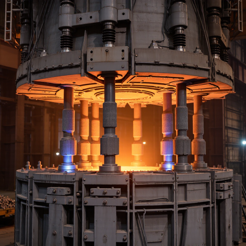
Define UHP Grade: Current Density Above 25 A/cm²
How to Choose the Right UHP Graphite Electrode?
UHP graphite electrodes are commonly associated with current densities above 25 A/cm². Current density means the operating current divided by the electrode’s cross-sectional area. This value helps determine whether an electrode can support demanding electric arc furnace conditions. It is not a label to accept blindly. Diameter, furnace power, arc stability, and duty cycle also affect the choice.
A practical selection starts with the furnace transformer and expected operating current. For example, a 600 mm electrode carrying 90 kA experiences a different thermal load than a smaller electrode at the same current. Check the manufacturer’s rated current range, electrical resistivity, bulk density, and flexural strength. Low resistivity can reduce voltage loss, while strong mechanical properties help resist vibration and thermal shock. The nipple connection deserves equal attention. Poor contact may create hot spots near the joint.
Inspect the electrode after use. Look for side oxidation, cracking, abnormal tip wear, and thread damage. These details reveal whether the selected grade matches the real furnace cycle. Cooling practices matter too. Excessive water near a hot electrode can increase thermal stress. That risk is often underestimated. A specification sheet may appear convincing, yet actual performance can differ with scrap mix, foamy slag, and power fluctuations. I would record current, voltage, consumption, and breakage by heat, then adjust the selection using those records. Some assumptions will be wrong. Measure twice.
How to Choose the Right UHP Graphite Electrode? - Define UHP Grade: Current Density Above 25 A/cm²
Ultra-high-power (UHP) graphite electrodes are selected primarily by allowable current density, electrode diameter, furnace operating conditions, mechanical strength, electrical resistivity, and thermal expansion behavior. The values below are representative industry ranges for petroleum-coke-based UHP electrodes and should be confirmed against the applicable supplier specification and furnace operating practice.
| Selection Dimension | Typical UHP Reference Range or Requirement | Why It Matters | Practical Selection Guidance |
|---|---|---|---|
| UHP classification | Allowable current density generally above 25 A/cm² | Defines the high-current operating capability associated with UHP electrodes. | Use the manufacturer's rated current and the furnace transformer conditions rather than relying on the grade name alone. |
| Current density calculation | J = I / A A = π × D² / 4 J = current density in A/cm²; I = current in amperes; D = electrode diameter in centimeters. | Converts furnace current and electrode size into a directly comparable operating value. | Calculate with the electrode cross-sectional area and verify that the result exceeds 25 A/cm² without exceeding the specified operating limit. |
| Electrode diameter | Common nominal diameters include approximately 300, 350, 400, 450, 500, 550, 600, 650, 700 and 750 mm. | Larger diameters carry more current at the same current density and can reduce the number of electrodes required. | Match diameter to the furnace hole pattern, holder capacity, roof opening, transformer rating and available electrode length. |
| Specific electrical resistivity | Typically about 4.5–6.5 μΩ·m for the electrode body; nipple values are often specified separately. | Lower resistivity reduces voltage loss and resistive heating in the electrode column. | Prefer lower resistivity when operating at high current, while also checking strength, oxidation exposure and thermal cycling performance. |
| Flexural strength | Typically about 8–12 MPa for UHP electrode bodies, depending on diameter and specification. | Higher strength improves resistance to mechanical loads, vibration and electromagnetic forces. | Choose the higher end of the range for high-current furnaces, long electrode columns, frequent additions and demanding charging conditions. |
| Bulk density | Typically about 1.68–1.78 g/cm³. | Higher density generally indicates reduced open porosity and improved resistance to gas penetration and mechanical damage. | Use bulk density together with porosity, strength and resistivity; density alone does not determine electrode quality. |
| Coefficient of thermal expansion | Typically about 0.9–1.5 × 10⁻⁶/K over a specified temperature interval. | Low thermal expansion helps reduce thermal stress and joint-related failures during rapid heating and cooling. | Prioritize low and consistent CTE when the furnace has frequent power changes, unstable arcs or severe thermal cycling. |
| Ash content | Commonly specified at approximately 0.2% or lower; the exact limit depends on the application. | Low ash reduces the risk of unwanted mineral contamination in steel and other melted products. | Use the strictest ash limit when product chemistry is sensitive to metallic or mineral impurities. |
| Nipple and joint compatibility | Joint design, thread form, pitch, taper and dimensions must match the electrode system exactly. | The joint transfers current and mechanical load between electrode sections; incompatibility can cause hot spots or breakage. | Do not mix components with different thread standards or dimensional tolerances unless compatibility has been formally verified. |
| Operating environment | Consider furnace type, steel grade, scrap density, arc stability, foamy slag practice, oxygen injection and charging pattern. | Actual electrode consumption and breakage depend on the whole process, not only on the electrode's nominal grade. | For unstable arcs, high oxygen use or severe thermal cycling, select a specification with strong mechanical properties and low CTE. |
| Nominal Electrode Diameter | Cross-Sectional Area | Current at 25 A/cm² | Illustrative Current Band at 25–40 A/cm² | Typical Application Consideration |
|---|---|---|---|---|
| 300 mm | 706.9 cm² | 17.7 kA | 17.7–28.3 kA | Smaller high-power furnaces or installations with limited electrode-hole dimensions. |
| 400 mm | 1,256.6 cm² | 31.4 kA | 31.4–50.3 kA | Medium-size EAF applications requiring high current with moderate electrode diameter. |
| 500 mm | 1,963.5 cm² | 49.1 kA | 49.1–78.5 kA | High-power operation where transformer capacity and roof clearance support a larger electrode. |
| 600 mm | 2,827.4 cm² | 70.7 kA | 70.7–113.1 kA | Large EAFs and high-current operating regimes; joint strength and thermal uniformity become critical. |
| 700 mm | 3,848.5 cm² | 96.2 kA | 96.2–153.9 kA | Very high-current furnaces requiring large electrode columns and substantial mechanical support. |
| 800 mm | 5,026.5 cm² | 125.7 kA | 125.7–201.1 kA | Specialized ultra-high-current installations; confirm furnace design and supplier availability before selection. |
Important: The current bands are mathematical examples based on 25–40 A/cm², not universal operating limits. The final choice must be checked against the electrode manufacturer's rated current, nipple specification, furnace transformer, cooling conditions, arc practice, electrode column length and applicable standards such as ASTM C783 or equivalent national specifications.